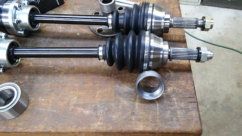
GT6 IRS swap with custom made: Lower Wishbone and chassis bracket, Vertical link and Hub machined for MGF bearing and CV joint/axle swap. (Not installed into car)
GT6 Lower Wish Bone Assembly Jig being made:


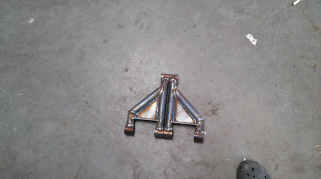

GT6 Lower Wish Bone welded up, and painted ready to install as replacement for OEM lower wishbones.


Grease Zerks added to the GT6 Rear Vertical Links.
MGF Bearing install into GT6 rear Vertical Links:


Inner hub sleeves made, with a 0.001" interference fit,
with 45 degree champher to match OEM champher.
Sleeves pressed onto hubs, and are purposely larger
OD and longer than the stock inner end of the hub, so
it can be turned down to correct size on the Lathe.

Facing the hub sleeve down to size

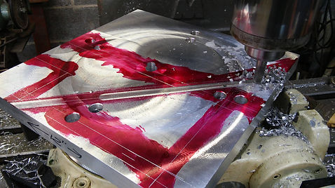
Boring the Vertical link for the MGF bearing.

Bored under size by 0.000" for light press fit.
MGF inner side, inner race support turned.

Cir-clip groove being cut.

Support on CV Shaft

Race supports on both shafts.

CAD drawing of Vertical Link, CV, MGF bearing and Hub.

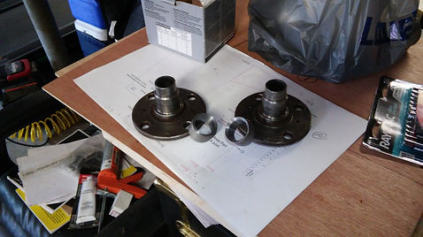
Hub stems (with sleeves) turned down to same size as the inner race ID of the MGF bearing for a firm but not hard press fit, also at the inner side of the hub where the bearing goes on there is an “Easy on” turned in about 1/8” for fitting/lining up the bearing so it will press on evenly. Both the Hubs and the MGF inner support pieces have also been painted. I will also use loctite 620 bearing retaining adhesive here also for the ID of the MGF bearing.

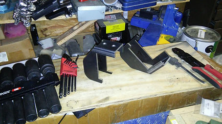
Next I ordered those rear wishbone inner pivot chassis/frame brackets from a UK vendor. When the bracket came in I noted it was flimsy about 14ga. and they were not robust enough in my book. So, using it as a template, made a drawing and made a bending jig for a pair that was made from 3/16” mild steel plate.
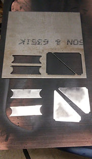
First I drew out the bracket profiles and had them cut on a waterjet.

Then I drew up a bending jig to bend them, and made it out of scrap aluminum blocks for my 20 ton press.

Base bending jig on the press

I made a pair of “Trial” brackets cut with a plasma torch and drilled out on my press more just to see
How the bending jig would do before bending my water jet cut profiles. This pic shows how the
Bracket it held to the bending foot so it does not bow
in the middle while bending the sides up.
I cut folding grooves along the bend lines using a 90 degree cutter, cut to ½ the plate depth Note they are both cut together but attention is paid to make sure they are orientated to be mirrors of each other BEFORE any cutting was done!!!

Folding grooves done

Top of bracket is the middle, (once it is bent) reference and bend holding holes drilled

1st bracket mounted to foot and in position, ready to bend

Bending in process, the base plate probably needed to be thicker with a deeper bend pocket But, I just turned the bracket and foot on its side and pressed it the rest of the way closed so each wing was 90 degrees.
Both Brackets bent, I guess I could have drilled the camber adjustment holes prior to bending,
But, I want to make absolutely sure the holes where parallel across from each other in the wings. So set
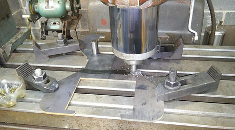
Them up on the mill table (right pic).

Drilling the camber adjustment holes to make sure they are directly across from each other and parallel to the top bracket surface (where the two reference holes are on the left).
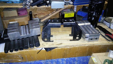
Both brackets done, all I will need to do is mig weld the internal folds for strength.
Assembling the complete modified IRS:

And the show begins; I will be fitting standard trunnion kit for assembling it all together.
But I think for final fitment, I will go to high performance “Poly” trunnion, wishbone, and
radius arm bush kits.
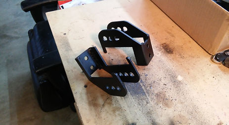
The “Thicker” lower wishbone frame mounting brackets out of 3/16” steel

MGF bearing and bore coated with Loctite 620 bearing retaining adhesive
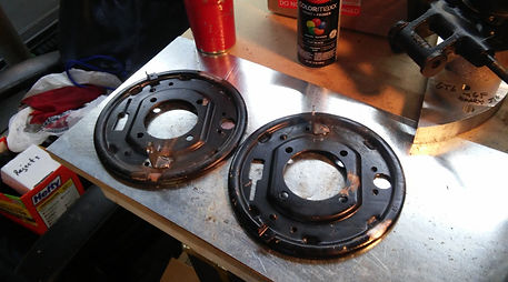
I made a brake line bracket, for the GT6 back plates, just like on the Spitfire back plates, since I am using CV shafts. I don’t have to worry about hitting the brake lines. Thus can keep the stock Spitfire brake line routing.
Brake tab (bracket), ready to MIG weld on

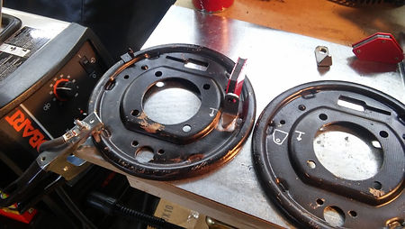
Both brake line brackets (Tabs) welded on, and back plates repainted flat black

Installing the brake parts

Passenger side done, showing “Inboard” side view

1st bracket welded on

MGF bearing installed, with Loctite and cir-clip in place

Brake parts installed

Both sides done, with the following mods:
-
Custom built lower wishbones
-
Custom built lower wishbone frame brackets
-
Vertical link and hub modified and machined for using a MGF bearings
-
Rover Lug Studs (12.5mm) replaced the stock lug studs
-
Will be using high performance “Poly” bushes for final fitment for the Trunnions, Radius Arms and Wishbone to frame bushes.
NOTE: GT6 rear IRS not installed yet.